
Plug & Perf: How Traditional Frac Plugs Work

Most completion engineers tasked with selecting the right tools for their horizontal multi-stage completions have seen or even held a frac plug. There are even several animations on YouTube from the major providers showing the plug and perf operation. Even with this material, it can be difficult to picture exactly how the plug is operating downhole during setting, frac, and the mill up. Without a clear understanding of this process, it can be difficult to appreciate the recommendations from the provider or what’s happening in the well throughout the process.
What I’m presenting below is a simple picture of how a traditional plug runs, sets, and then is milled. I’ve included some commentary on how the plug works along with what can cause issues. My mission is to equip you with the necessary information you can use to judge your plug selection with the details of its operation. My drawings are simple and imperfect and are designed to illustrate the general concepts of operation. If you have more detailed questions, please leave them in the comments or send me a direct message.
Traditional Plug Construction
A traditional composite plug will contain a mandrel, upper slip/cone, element, and lower slip/cone. The mandrel will provide the structure of the plug that the other components “ride” on and will either have profiles machined into it or have additional parts attached to constrain the components during run in, setting, and frac. The slips are designed to interact with the cone such that when forced together the slips move outward to touch the casing. The slips will have hardened edges that are designed to “bite” into the casing, locking them in place. The slips will be a full ring or individual segments that are held together with band of some sort. Either way, they are designed to stay together until the setting sequence breaks them apart allowing them to move up the cone and set into the casing.
For a frac plug, designed to only hold pressure from above, the lower slip will be designed to hold the full force of the frac and the upper slip will be designed to keep the plug, mainly the element, compressed after setting. The element is designed to compress under the setting force creating a seal between the ID of the casing wall and the mandrel. This seal will provide the isolation necessary to separate the well into two parts so that the zone above can be treated discretely. For a ball drop plug, a ball will be dropped from surface to land on the mandrel and complete the isolation.

Pump Down Considerations
The first test of a composite plug’s performance comes during the pump down operation. For this sequence a composite plug is made up to a wireline bottom hole assembly (BHA) that includes a plug, setting tool, and perforating guns. This BHA is dropped down to the kickoff point in a horizontal well and then pumps are used to deploy it to its intended location. During this operation it is critical that the components stay as assembled. The slips must stay together, otherwise they would contact the casing during deployment, move up their cone, and create a preset event.
The element must stay in place as well to avoid the same fate. With rubber elements, this can be difficult. The typical 5.5” plug, for instance, has an OD of 4-3/8” and the casing has an ID of 4.778” which leaves a small gap between the plug and the casing (just .2” per side). Depending on how fast the plug is moving and the flow rate of the pumped fluid, there can be a lot of bypass around this plug. As this bypass increases it will create a low-pressure zone around the plug that could cause the element to swell out and contact the casing. Because of this, it is critical to understand how much fluid is bypassing the plug during deployment and most providers will provide guidelines for how fast the plug must be moving at different pump rates. Operating outside of this guidance could cause an issue during deployment.
Setting
The setting of a plug is done by an explosive setting tool. Details on how the two main types of setting tools work can be found on previous articles here and here. The plug mandrel will be held static and the components will be forced together to set the tool. Usually the element will compress, then the slips will break, and move up the cones until they’re forced into the casing and are locked in place. Once the slips are set, the force generated by the setting tool will exceed the shear force of the plug shear media and the setting tool will shear off the plug leaving it autonomous in the well. After setting, part of the mandrel will be exposed above the newly compressed components. The length of this exposed mandrel will be equal to the amount of composite above the upper slip as assembled, plus the stroke length required to set the tool.

One of the critical design constraints of composite plug is the stroke required to set the tool. This length is governed by the stroke provided by the Baker Setting Tool, which is 5.875” for the E4-10 and 8.625” for the E4-20. If the tool requires more stroke than this, the setting tool will likely not shear off of the plug.
The performance of the upper slip, with this configuration, is critical just after setting. The upper slip must bite into the casing to lock the compression into the element and maintain the seal. If the upper slip does not perform as designed, the element will be able to relax and you will lose your seal. What’s interesting is that the element plays a role in maintaining its own compression. If the element didn’t create an opposing force onto the upper cone, it wouldn’t keep support under the slip required to stay engaged with the casing. Without the “back pressure” from the compressed element, the upper slip would not perform its job.
During the Frac
After setting, the wireline BHA will be used to perforate the casing above the plug and then removed from the well. The surface frac equipment will then be rigged up. For a ball drop plug, the majority of what’s run, a ball will be dropped from surface. Once reaching the horizontal part of the well it will be pumped down to land on the plug, isolating the well into two sections. When the ball lands and the frac begins, the pressure will force the mandrel downward until it interacts with the top of the upper slip. The seal must be maintained as it slides through the element.
This results in a length of mandrel below the plug equal to the stroke plus the bottom of the plug. This doesn’t really affect the setting or frac components of the plug’s performance but can have an impact on mill up.

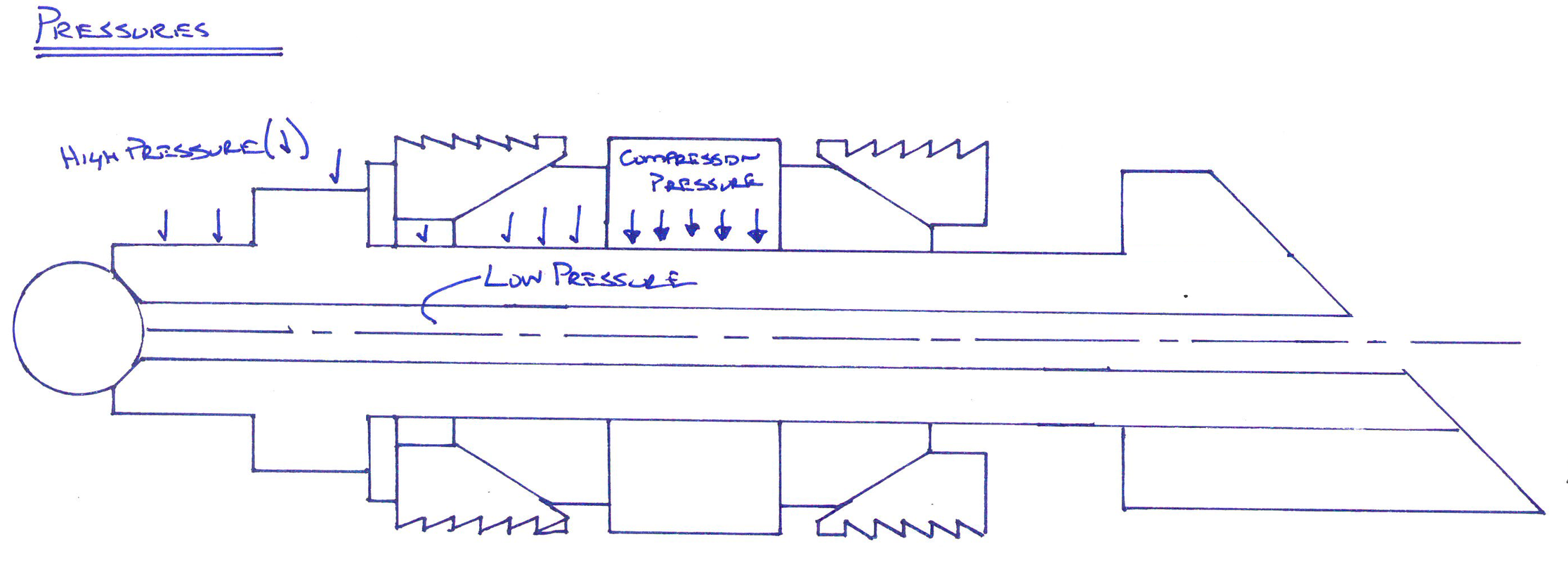
During the stimulation there is high pressure exerted on the top side of the plug, with lower pressures on the bottom of the plug. This differential in pressure dictates how the plug must be designed to withstand the forces exerted. As you can see below, the pressure from the frac is exerted on the ball, and the mandrel above the element. Below the ball and the element there is only the pressure from the reservoir. This results in a collapse pressure exerted on the mandrel above the seal. At the seal the mandrel must withstand the collapse pressure and the compression of the element.
The lower slip and cone must withstand the mechanical force generated onto the element and plug from the difference in pressures. The plug provider must use material thicknesses and strengths to achieve a plug that can perform under these conditions. Typically, a failure of a traditional frac plug is caused by the collapse of the lower cone/mandrel causing the lower slips to lose their bite. The performance of the tool is reliant on the strength of the composite.
Another concern for designers is the element’s performance during the high pressure and temperature situations. The rubber element is flexible and will become even more flexible under hot temperatures. When high pressure is added to the mix it can result in the rubber element flowing in the direction of the pressure. Many of the traditional plugs on the market will include an element back up system that is designed to expand with the element as it is set and then provide structure to keep the element in place during the high-pressure phase of the frac.
Mill Up
The final phase of the composite frac plug’s performance is the mill up. I have a couple articles here and here regarding what bit/mill to select for each size plug and why (here and here). Beyond this, traditional plugs mill up in a certain way that drives the recommendations that providers make to their customers.
The plug will be in the same configuration with the mandrel shifted down. Most composite frac plugs have a mandrel that is a tube. The only thing keeping the mandrel from spinning during the milling operation is the friction exerted on the mandrel from the element. The milling operation will have to overcome this spinning to mill effectively.
If you remember earlier, the lower slip’s job is to hold the plug from moving downward during the frac. It also provides this function during the mill up. The forces against a frac plug during the frac is equal to (up to) 10,000 psi times the area of the casing ID. For 5.5” 20# casing this can be up to 200,000 lbs. When milling out the weight on the bit can be up to 10,000 lbs, much less than what the slips are designed to handle. The slips will hold the plug to be milled up until the milling gets down to the lower slips. During the milling of the lower slips the weight of the string will also push the cone downward further holding the slips in place until enough is milled such that the slips can no longer hold the weight and vibration of the milling operation.

When the lower slips give up the remaining slip pieces, lower cone, and mandrel/lower support will become loose in the casing and will generally be washed down to the next plug for full milling. Depending on the design of the slip, these hardened pieces and the large “stump” from the mandrel could cause longer wash times as the pieces move downward. Once these remaining pieces get to the next plug they must become locked in for the mill/bit to establish a cutting pattern. With a traditional plug these pieces must lock onto the top of the next plug and the ball that has landed on the plug as well. If there isn’t enough weight on bit the ball can act as a bearing, keeping the parts spinning and not milling out. My understanding and experience with mill ups has shown that if the mill up times are have greatly increased during an operation, it is probably due to the components spinning and not locking into a cutting pattern.
During the milling operation it is critical that the parts break up into pieces that can be circulated past the milling BHA and make it to surface without impacting the operation or removal of the milling BHA from the well.
Entire Operation
The three phases of the composite plug’s life cycle are critical to deliver the value they promise. All composite plug designs have their individual technical differentiators that allow them to provide features and benefits to improve upon the general concepts discussed above. Understanding the general function and performance of these features can help you to make the best decision for your well completion.